Standard End Plates
- General Overview
- Tips and Tricks
- Related Tools
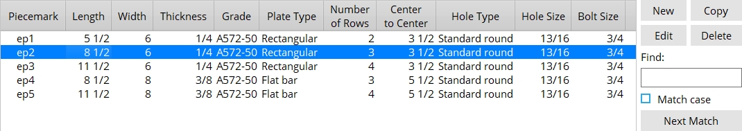
Standard End Plates
New: Opens the Standard End Plate Options screen so you can add a new plate to the schedule.
Copy: Opens the Standard End Plate Options screen and copies the settings of the selected plate so you can add a new plate to the schedule. This button is deactivated when a plate is not selected.
Edit: Opens the Standard End Plate Options screen so you can edit the selected plate. This button is deactivated when a plate is not selected.
Delete: Deletes the selected plate.
Find: The Find widget searches the schedule for piecemarks and selects the closest match. Match case performs a case-sensitive search. Next Match cycles to the next piecemark that closely matches the search criteria.
Standard End Plate Options
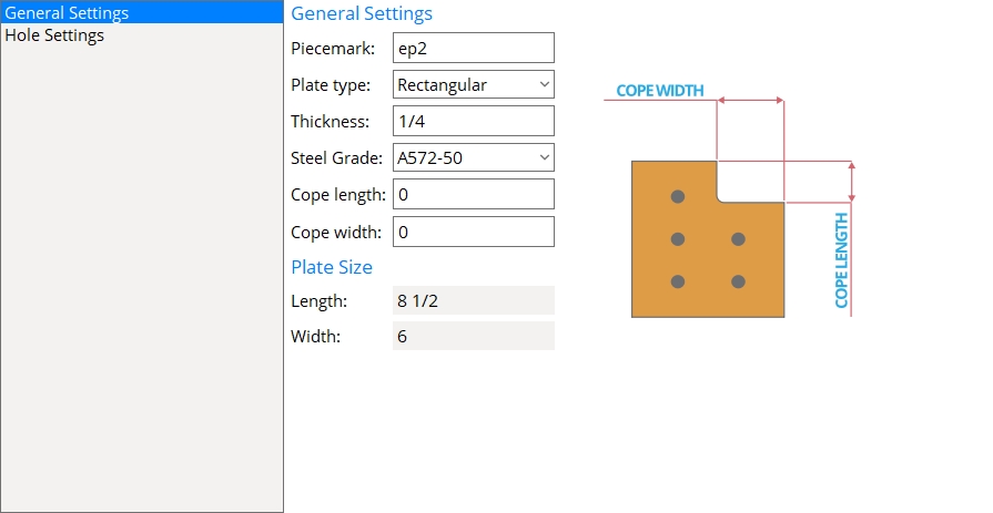
General Settings
Piecemark: The standard submaterial mark (standard piecemark up to 61 characters) that you want assigned to a standard non-moment end plate.
Note: The piecemark entered here must be unique. If the piecemark you enter is already assigned to another material, a red exclamation point appears
( and prevents you from clicking OK until you change your entry to a unique piecemark.)
Plate type: Rectangular or Flat bar.
Select Rectangular if no listing on the Preferred Flat Bar Sizes window matches the Thickness and Width of this plate.
Select Flat Bar if the Preferred Flat Bar Sizes window does have a listing that matches the Thickness and Width of this plate.
Setup: Connection design uses plate material for end plates unless there is a suitable flat bar listed on the Preferred Flat Bar Sizes screen.
Thickness: The Material thickness of the plate.
t = thickness of end plate.
Steel Grade: Any steel grade from Home > Project Settings > Job > Material Grades > Plate Grades or Flat Bar Grades.
Cope length: The vertical distance of the cope measured parallel to the Length of the end plate.
|
l = cope length. |
Connection design: To get connection design to generate a cope on an end plate, set the end plate to have a Safety-notch connection. Connection design generates a Cope length that is equal to two times the Vertical edge distance of the plate.
Cope width: The horizontal distance of the cope measured parallel to the Width of the end plate.
|
w = cope width. |
Connection design: To get connection design to generate a cope on an end plate, set the end plate to have a Safety-notch connection. Connection design generates a Cope width that is equal to two times the Horizontal edge distance of the plate.
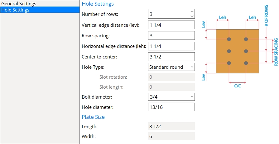
Length: (READ-ONLY) The Order length of the of the end plate is automatically calculated from the Vertical edge distance (lev), Row spacing, and Number of rows.
Width: (READ-ONLY) The Material width of the of the end plate is automatically calculated from the Horizontal edge distance (leh) and the Center to center hole distance.
Hole Settings
Number of rows: The quantity of rows of holes in the end plate.
|
Number of rows = 3 |
Vertical edge distance (lev): The vertical distance from the top or bottom edge of the end plate to the center of the nearest hole.
|
lev = vertical edge distance |
Row spacing: The vertical distance between the centers of any two adjacent holes.
|
s = row spacing |
Horizontal edge distance (leh): The horizontal distance from the edge of the plate to the center of the nearest column of holes.
|
leh = horizontal edge distance |
Center to center: The horizontal distance between the columns of holes in the end plate.
|
g = center-to-center between columns of holes. |
Hole Type: Standard roundor Short slot or Oversize or Long slot or User slot #1 or User slot #2.

Slot rotation: A positive or negative number of degrees (from 90 to -90 ). This applies when the Hole type is Long slot, Short slot, or User slot #1 / #2. Slot rotations can be modeled to a precision of 0.1 degree.
![]()
Slot length: The distance between the two ends of a slot. This applies when the Hole type is Long slot or Short slot.
| slot length |
|
|
Bolt diameter: The diameter of the shank of the bolt to be used for connecting the end plate to the supporting member.
| diameter |
|
Hole diameter: The diameter of holes that are in the end plate. The default hole diameter is calculated by the Hole type and Bolt diameter according to your selected connection design method.


|
|
OK (or the Enter key) closes this screen and applies the settings.
Cancel (or the Esc key) closes this screen without saving any changes.
Reset undoes all changes made to this screen since you first opened it. The screen remains open.
- Red or yellow exclamation point icons

- To open this screen, your current Fabricator needs to be the Master Fabricator. The option to Change Fabricator can be found on the SDS2 Home window window.
- To manually add a plate from this window, select its standard piecemark when adding an existing material.
- Standard piecemarks (topic)
- Process and Create Solids > Create Solids > Assigning piecemarks
- End Plate Settings (Project Settings)

